TD — Sequential Logic
Overview
D Flip-Flop with Enable
We would like to construct a D flip-flop with a synchronous and active high reset and an additional input en:
- When en is high, the flip-flop works as usual
- When en is low, the flip-flop is frozen such that the output Q maintains its value even after a rising clock edge
Question 1: Using paper and pencil, draw a schematics implementing the above specification, using a standard D flip-flop and additional logic gates.
In order to verify if your design is correct, switch to the terminal and go to root folder of the archive. Type
cd dff
logisim dff-impl.circ &
to open the template circuit. Once you are done with your design, execute the testbench by typing
make
In the waveform viewer, compare the two waveforms of Q.
Adressable Register
We now want to build a first basic block of a future processor core: An addressable register bank. Such a module contains multiple registers, each of which is build by several flip-flops. The register bank has an address input that selects the corresponding register and shows its contents on the dout data output. Additionally, there is a data input (din) and a write signal. If write is active at the rising edge of the clock, the value of din will be written to the register selected by addr. Finally, there is a reset signal that will reset all register values to zero when active.
The design files for the addressable register are in the reg subdirectory of
the source archive. Execute the following commands to start building and
simulating your circuit:
cd reg
logisim reg-impl.circ &
make
In the circuit template, there are already four 8-bit registers, labeled Reg 0 to Reg 3. Note that each of the registers has several functional inputs:
- The Clock input needs to be connected to the global clock signal for the register to work
- The Enable input controls the writing of the regiser: Its value is updated on the rising edge of the clock if Enable is active
- The Clear input (labeled 0) resets the value of the register to 0 if active
Question 1: Implement the reading logic: Depending on the address input, redirect the value of the correct flip-flop to the circuit's data output dout. Which circuit component should be used for this purpose? Find and use a pre-defined component in the available libraries.
Question 2: Implement the writing logic: If the write input is high, depending on the address input, update the correct flip-flop with the value of the data input din. Again, there are useful pre-defined components in the library, which can be used to implement the writing logic. Don't forget to connect the reset signal.
In order to test your design, execute the testbench by typing
make
In the waveform viewer, compare the two waveforms of the datat output dout.
Serial to Parallel Conversion
Serial communications are used in many applications. You might have heard of the USB standard, which stands for Universal Serial Bus. Other (simpler) protocols include SPI or I2C. The advantage of transmitting data serially (i.e. one bit at a time) is the small number of required signals, which reduces the number of input and output pins of integrated circuits and the hardware costs for transmission cables. However, since in a computer, data is stored as words, for example in chunks of 8 bits, we need to somehow reconstruct the (parallel) representation from the serial data received over time.
Consider the following specification:
- We are receiving in a synchronous manner, a sequence of bits on the input (serial in)
- We would like to transform the received data to words of 4 bit and present them at the output (parallel out)
- The bits are received in the order of their indices, i.e. the first bit received shall correspond to the least significant bit of the output
- An additional output valid shall indicate whenever the output is valid (i.e. whenever a full sequence of four bits has been received)
Question 1: Implement the serial-to-parallel converter using flip-flops and basic logic gates. You can leave out the generation of the valid signal and add it later.
Once you are satisfied with your design, implement it in logism and test it using the provided testbench:
cd ser2par
logisim ser2par-impl.circ &
make
Below is a timing diagram showing the transmission of three consecutive messages: 1001, 0101, and 1100.
Counters
In this exercise we will play with counters. The basic structure of a counter has been presented during the lecture:

The above figure shows an 8 bit counter (with a negative reset), which counts modulo 256. It consists basically of a register and an adder doing the arithmetics. Starting from this simple structure, we are going to add some more interesting functionality.
You can find the logisim environment for this exercise in the subdirectory count. Execute the following commands from the base directory of the exercise archive in order to open the circuit template in logisim:
cd count
logisim counter-impl.circ &
In this exercise, there is no specification, you can simulate your circuit in two different ways. In logisim, there is a top level circuit that drives the counter and shows its value on a 7 segment display:
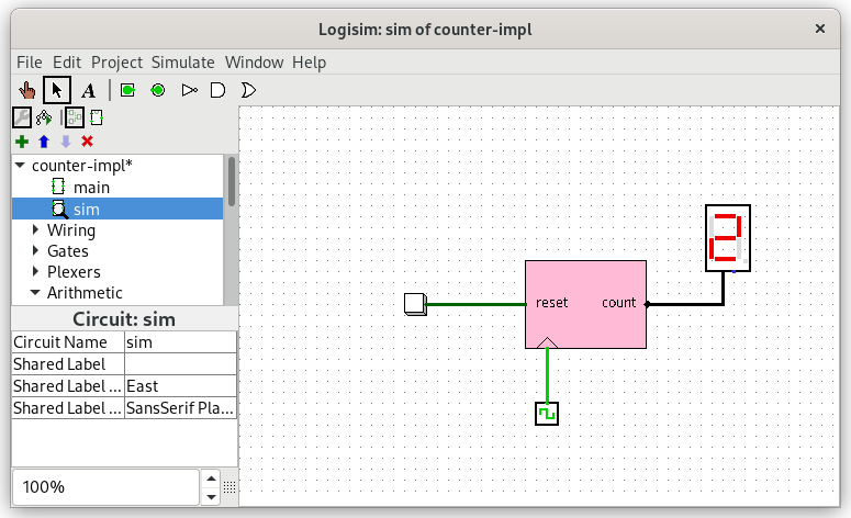
You can advance time by pressing ctrl-T and reset the simulation pressing ctrl-R.
The other possibility is to run logisim from the command line and inspect the waveform by typing make.
Question 1: Open the main circuit and implement a 4-bit modulo counter (thus counting from 0 to 15 and starting over at 0 again) with a positive reset. Do not use the ready-made counter component of the logisim library (we know it's there), but a register and any arithmetic or logic components you need. You can use the reset provided by the register component or use additional combinatorial logic. Simulate your counter to check if it works correctly.
Question 2: Instead of a modulo counter, we would like to build a counter with saturation arithmetic. This means that it will count up to 15 (shown as F on the 7 segment display) and then keep its value until is is reset.
Question 3: This time, we would like to have an up-and-down counter: It shall start with 0 and count up to 15, then decrement its value until it reaches 0, then start incrementing again.