Solutions for the RISC-V Exercises
Overview
You can download a source code archive with the completed logisim circuits.
R-Type Instructions
ALU
Here is a working solution for the ALU:
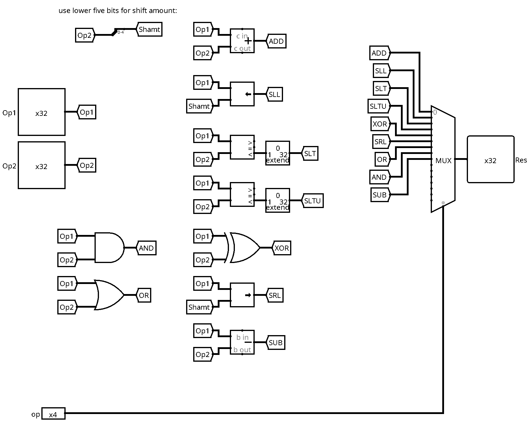
It is basically a big multiplexer that selects the adequate result among the different computations. Each computation has been realised by a basic gate or a block from the logisim arithmetic library. Note that we have extracted the lower five bits of the second input for the shift operations.
Decode Unit
Here is a working decode unit for R-type instructions:
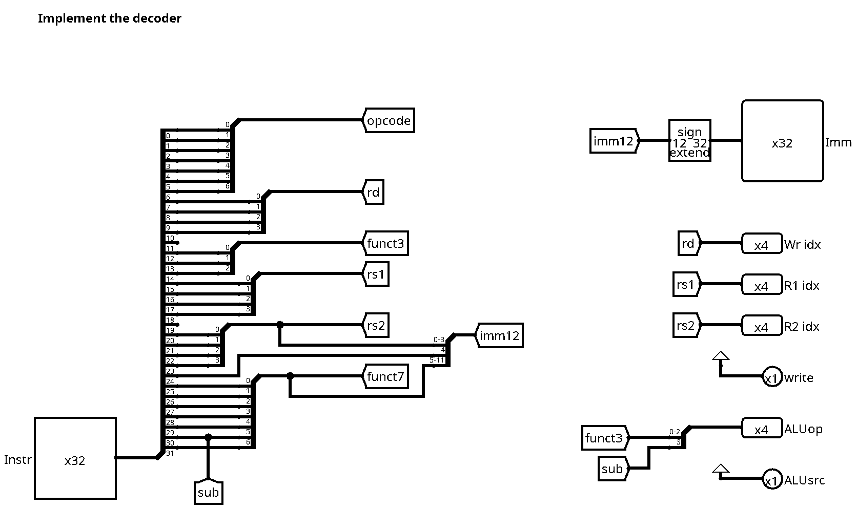
For R-type instructions, there is actually not much to do, since most outputs are just redirections of wires from the instruction word. We have extracted bit 30 (cf label sub), which is used together with the funct3 field to construct the ALU operation output. For now, both write and ALUsrc outputs can be hard wired to the value 1: All instructions write the register file, and all of them use the second register for ALU computations.
We have already prepared the immediate constant, even if it is not used by R-type instructions. We make use of the bit extender module of the logisim library for sign extension from 12 to 32 bits.
Immediate Instructions
Here is the new version of the decode unit:
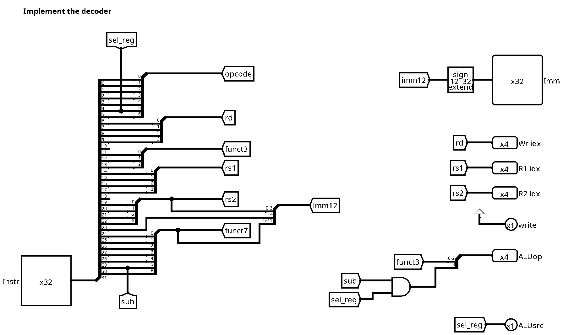
There are two changes with respect to the previous version:
- We now use bit 5 of the opcode to decide on the second ALU source
- The same bit needs to be taken into account to determine the ALU operation
For the first part (ALU source), note that the opcodes for R-type instructions
(0110011) and immediate instructions (0010011) only differ in bit 5. We can
therefore directly use this bit (extracted to the label sel_reg) to select
the ALU source, where 1 corresponds to the second regiser, and 0 to the sign
extended immediate value.
For the second part, note that the only R-type instruction making use of bit 30
for the ALU operation is sub. For all other R-type instructions, this bit is
zero, and therefore also the most significant bit of the ALUop output. Note
also that there is no subtract immediate instruction, all immediate
instructions will set the MSB of ALUop to zero. We need to be careful not to
use bit 30 (label sub) for immediate instructions, since bit 30 is part of the
immediate constant encoded in the instruction word. It could be 1 or 0,
depending on the value of the constant. This is why we need to add an AND gate
in order to set the MSB of ALUop to zero for all immediate instructions.
Load instruction
Data Path
Here is the data path for the load word instruction lw:

Let's zoom in on the interesting part:
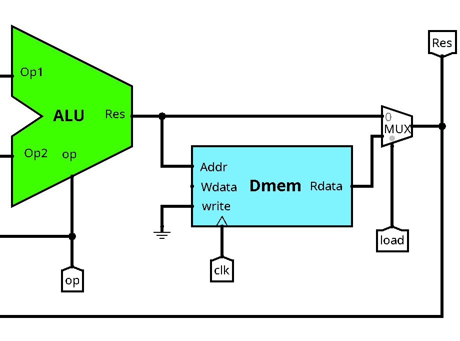
The address of the data memory (first register plus constant offset) will be
computed by the ALU, this corresponds actually to the same computation as for
the addi instruction. For the moment, we can leave the data input of the
memory unconnected, we will need it later to store data. Don't forget to connect
the clock and to connect the write input to 0 (ground symbol).
We now have two different possibilities for the data written back to the register file: It could be the ALU result (for R-type and immediate instructions) or the data read from the data memory (for load instructions). We need to add another multiplexer in order to choose among these two options. The select input is connected to the new control signal load.
Decode Unit
Here is the new version of the decode unit, taking into account lw:
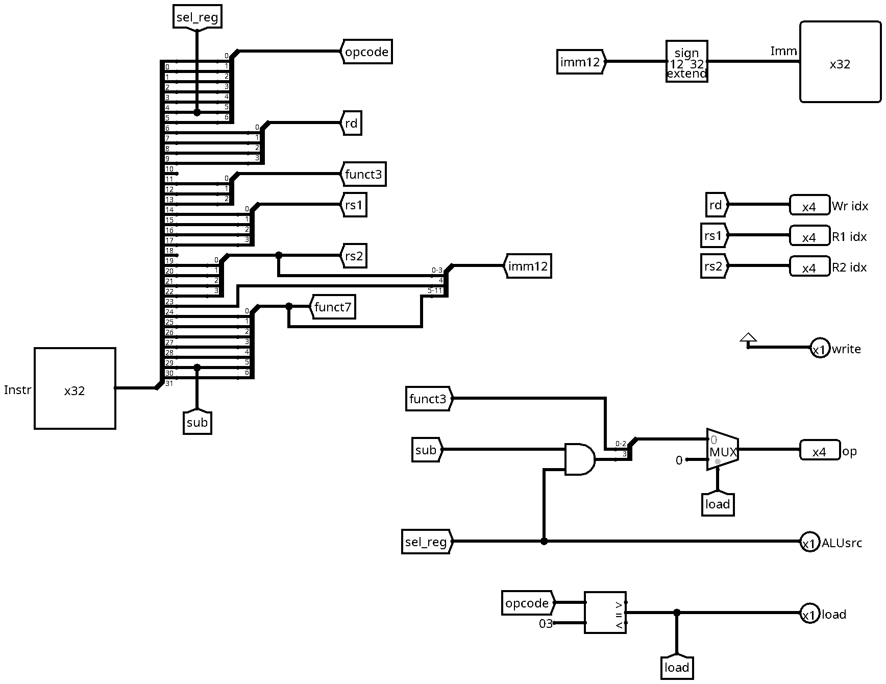
There are two changes with respect to the previous version:
- We need to compute the new load signal
- We need to update the computation of the ALUop signal
For the first part, we can simply use a comparator to check if the opcode
corresponds to the lw instruction (0000011 or 3 in decimal).
Remember that we want the ALU to perform an addition of the first register and the immediate constant from the instruction word. So we need to make sure that
- The ALUsrc chooses the immediate value for the second operand (0)
- The ALUop is set to addition (0)
Looking at the lw opcode, we notice that we can reuse bit 5 (label sel_reg)
for the ALU source, since it is 0. Unfortunately, we cannot reuse the funct3
field for the ALU operation, since for load instructions, this field indicates
the size of the loaded data (we only do word size loads here). So instead we add
a multiplexer that will set the ALU operation to zero if we are decoding a load
instruction. For the select input of the multiplexer, we can simply use the
newly created load signal.
Store Instruction
Data Path
There are two changes in the data path:
- We need to connect the new store signal to the write control input of the data memory
- We need to connect the second register output to the Wdata input of the data memory
Decode Unit
Here is a working implementation of the decode unit for store instructions:
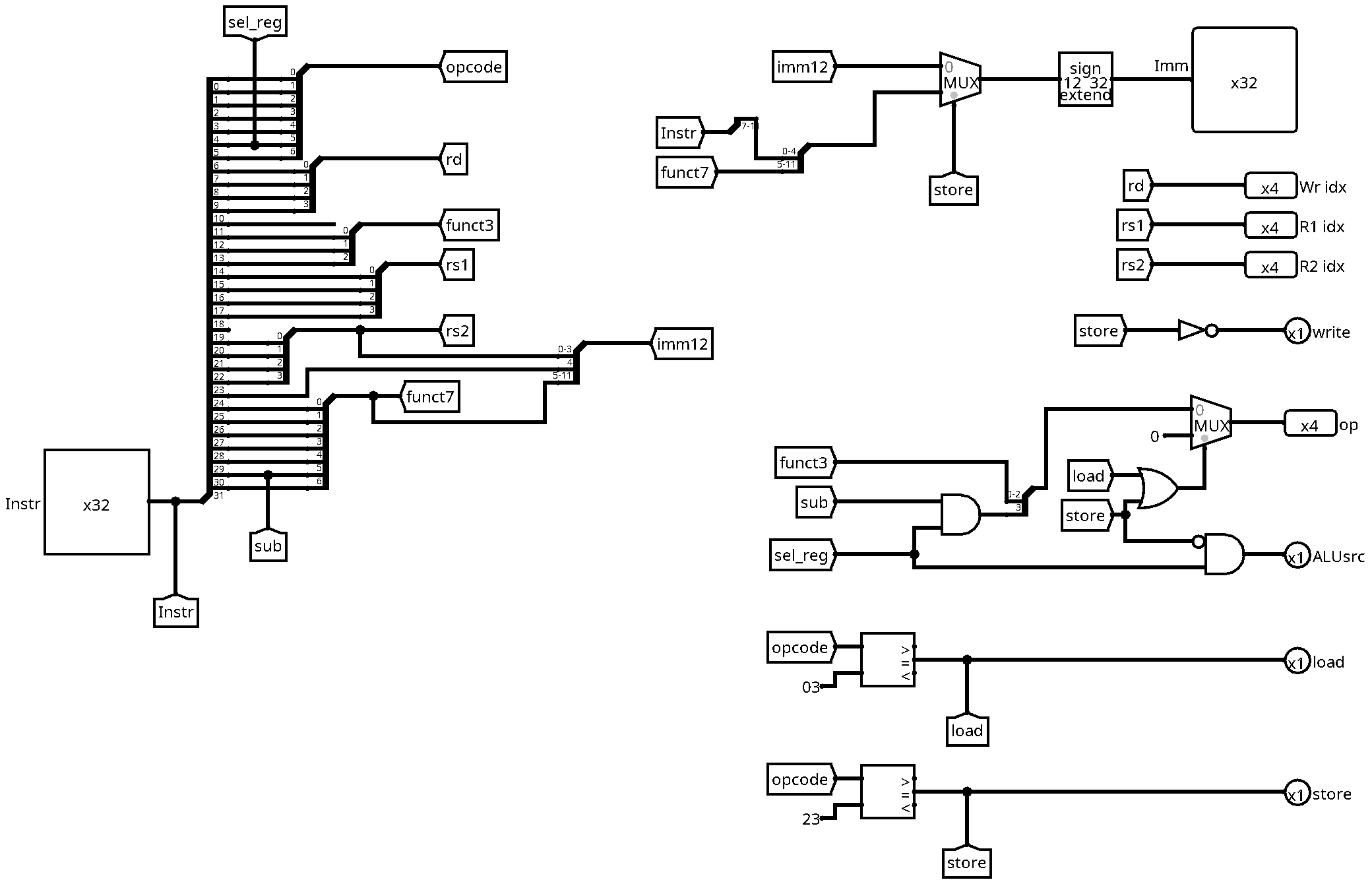
There are several changes:
- The new store control signal
- The immediate value
- The ALU operation
- The ALU source
- The write signal
We can compute the store control signal in the same way as the load signal,
by comparing the opcode with the value for store instructions (0100011 or 23
in hexadecimal). The store signal will be useful for the computation of the
remaining control signals.
The immediate value needs to be adapted since it is encoded differently for store instructions. The reason is that we have two source registers, but no destination register. The design decision of the RISC-V creators was to always keep register addresses at the same place in the intruction word. Therefore, the five lower bits of the immediate value cannot be stored in bit 20 to 24, since this is the place for the second source register address. Instead, we use the place freed by the destination register (bits 7 to 11). In order to distinguish between these two immediate encodings, we add a multiplexer with the store signal as select input.
The ALU operation is the same as for load instructions (0), since we need to compute the sum of the first register and the immediate value. We just add a condition to the already existing multiplexer by adding an OR gate, taking load and store as inputs.
Regarding the ALU source, unfortunately, the store instruction breaks the simple logic that worked for all previous instructions, since the opcode bit number 5 (labeled sel_reg) is 1 for store, but ALUsrc must be 0 in order to select the immediate value as second operand. We can fix this by adding an AND gate with sel_reg and the negation of store as inputs. In this way, ALUsrc is set to 0 whenever we decode a store instruction.
Finally, we need to adapt the write signal, since store instructions do not write the register file (they write to the memory instead). The solution is to define write as the negation of store.