Homework: Building an Arithmetic-Logic Unit
Introduction
During the previous exercise, we have constructed an (optimised) adder/subtractor, for which we can select the performed operation with an input control signal. This is already quite nice. In this exercise however we would like to add even more operations, generalising our adder/subtractor to an Arithmetic-Logic Unit (ALU). As we will see later in the lecture, the ALU is a central component in every processor. It does an important part of the actual work when executing a program: adding or subtracting numbers, comparing values, shifting bits to the left or to the right, bit-wise logic operations etc.
Specification
How does such an ALU look like? We will keep the interface simple: There are two data inputs and , both representing 8 bit signed integers, and a single data output , also an 8 bit signed integer. Instead of a single control input, we have a 3 bit input , which selects among eight different operations:
| Name | Operation | Description | |
|---|---|---|---|
| 0 | ADD | Signed addition | |
| 1 | SLL | Left shift by positions | |
| 2 | SLT | Set less than | |
| 3 | SUB | Signed subtraction | |
| 4 | XOR | Bit-wise exclusive or | |
| 5 | SRL | Right shift by positions | |
| 6 | OR | Bit-wise or | |
| 7 | AND | Bit-wise and |
Addition and subtraction should be obvious. For the three bit-wise logic operations XOR, OR, and AND, the -ith bit of the output results from the respective logic operation between the -th bits of the inputs.
For left or right shifting, the second input represents the shift amount, i.e. the number of positions that the input is shifted. The direction corresponds to the bit order where the most significant bit (MSB) is on the left and the least significant bit (LSB) is on the right. Left shifting will shift out the most significant bits and fill up the least significant bits with zeros. Right shifting will shift out the least significant bits and fill up the most significant bits with zeros. Since we interpret the input as an unsigned integer (the shift amount), only the lower three bits of should be used, allowing for shift amounts between zero and seven.
Finally, the SLT operation compares two signed integers. If is less than , the output will be (i.e. only the LSB is one and the remaining bits are zero), otherwise the output will be .
Implementation
During the exercise on building an adder-subtractor, the goal was to create a combinatorial circuit optimized for its area: We found out that adding and subtracting could be done by a shared adder circuit, and switching the inputs depending on the requested operation. In this homework, the only goal is functional correctness, i.e. we do not care about the number of gates needed to build the final circuit. This means for example that you can use two separate operators for addition and subtraction without feeling bad about it.
As a starting point, we provide a circuit template and a testbench. Go to the alu subdirectory of the archive and open the file alu.circ:
cd alu
logisim alu.circ &
Note that for each of the eight operations (including shifting and comparison), there is a pre-defined component available in the LogiSim library. Feel free to explore the available components and to instantiate them in your implementation.
Testing your ciruit
In order to run the tests, execute the following command:
make
Do not forget to save your current implementation before running the tests. You should see a wave trace coming up like this:
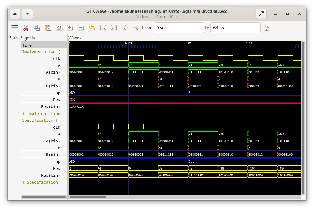
In the trace, the input and output signals and are shown twice, once in binary format and once as signed integers. It's the same signals. Even if the circuit is combinatorial, there is a clock signal. It is only used to generate the test sequence. There are four tests for each of the eight arithmetic and logic operations. Your goal is to reproduce the exact same results for all of the tests (compare between implementation and specification).