Homework — Finite State Machines
Introduction to Finite State Machines (FSMs)
A Finite State Machine (FSM) provides a systematic way to design sequential logic for control sequences.
Structure
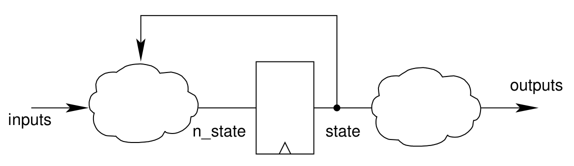
The figure shows the generic structure of a synchronous sequential system.
The outputs of the system depend on some internal state (state in the figure).
Depending on this state and the inputs of the system, we can compute combinatorially its next state value (n_state in the figure) that will replace the state value at the next clock edge.
The outputs of the system will only depend on its state value (combinatorially).
This kind of synchronous system is called a Moore Finite State Machine (FSM).
The name (FSM) comes from the fact that with this structure, the number of states that a system can have is limited (and thus finite) by the size of the state register.
Methodology
Starting from a functional specification.
Draw a state transition diagram

Each node is one of the possible states of the system. The arcs represent the transitions from one state to the other. The label on each arc represents the condition for which the transition is taken (functions of the inputs).
Remember that this diagram represents the state transitions of a synchronous system. The evolution of the state can only happen at the clock edge.
In this example:
S0represents the initial state (i.e. after an active reset)- there is an explicit transition from
S0toS1whencis high, - there is an implicit transition, if
cis not high, the state remainsS0
- there is an explicit transition from
- From
S1toS2there is an unlabeled arc, this indicates that we will systematically go fromS1toS2at the next clock cycle.
State encoding
Represent each state by a numerical value.
For example:
| State | Encoding |
|---|---|
| S0 | 00 (0) |
| S1 | 01 (1) |
| S2 | 10 (2) |
This encoding is arbitrary and not unique.
State transitions
The state transition function can be constructed using a truth table. For the previous example:
| State | e | c | n_state |
|---|---|---|---|
| S0 (00) | x | 1 | S1 (01) |
| S0 (00) | x | 0 | S0 (00) |
| S1 (01) | x | x | S2 (10) |
| S2 (10) | 0 | x | S1 (01) |
| S2 (10) | 1 | x | S0 (00) |
This table describes the combinatorial function to compute the next state. Note that 'x' in the table stands for don't care, i.e. the given transition will be the same for any value (0 or 1) of the respective input. Note also that there is one unreachable state, which corresponds to the value 11.
From the above table, we can derive Boolean equations for the state transition function. Ther is only one transition to S2, and it is always taken from state S1 so the function for the most significant bit can simply be expressed as
\[ \text{n_state}_1 = \overline{\text{state}_1} \cdot \text{state}_0 \]
There are two transitions to state S1, setting the least significant bit of the state encoding to 1. The function can thus be expressed by
\[ \text{n_state}_0 = \overline{\text{state}_1} \cdot \overline{\text{state}_0} \cdot \text{c} + \text{state}_1 \cdot \overline{\text{state}_0} \cdot \overline{\text{e}} \]
Exercise
We want to design a finite state machine corresponding to the following specification:
- We want to control two LEDs via the output signals \(LED_0\) and \(LED_1\)
- The only input signal besides the clock \(clk\) and an asynchronous \(reset\) is a \(button\)
- In the initial state, both LEDs are off
- When the button is pressed once, \(LED_0\) is turned on
- When the button is pressed once more, \(LED_0\) is turned off again
- When the button is pressed once more, \(LED_1\) is turned on
- When the button is pressed once more, the system return to the initial state (both LEDs switched off)
Note: The clock signal is very fast compared to any input action performed using a big human finger on the button. Pressing the button will result in the corresponding input signal going high for many cycles. So you need to somehow ensure that only a single change of the lights is triggered by a button press.
Question 1: Draw the state transition graph of an FSM realising the above specification. Indicate the conditions of the state transitions as well as the output values corresponding to the states. How many states does your solution need?
There are several possible solutions, one of which is a pure state machine solution, while another one combines a state machine with an edge detector. In the following we will consider this latter solution and assume that the button is connected to a rising edge detector, which generates the signal \(top\) on each rising edge of the button.
Question 2: Draw again the state transition graph, this time using \(top\) as input instead of the button.
In the following, you will construct a circuit realising the finite state machine. Let's revise the general structure of an FSM's hardware implementation:
Here, the cloud on the left hand side represents the next state function, while the one on the right hand side represnets the output function. The current state is stored in the central register. Both next state and output function are combinatorial.
Question 3: Choose a state encoding for your state machine. First determine the number of bits (and therefore flip-flops) needed to represent all of your states. Then establish a mapping of your states to concrete values of the flip-flops.
We will call the output signals of the state register \(S_i\) in the following.
Question 4: Establish the output function. In a first step, fill in a truth table, mapping your state encoding to the outputs \(LED_0\) and \(LED_1\). For example, if your states are encoded in two bits, this corresponds to the following table:
| \(S_0\) | \(S_1\) | \(LED_0\) | \(LED_1\) |
|---|---|---|---|
| 0 | 0 | ||
| 0 | 1 | ||
| 1 | 0 | ||
| 1 | 1 |
Question 5: From the truth table, derive the Boolean equations for both output signals.
Question 6: Establish the next state function. Start again with a truth table. This time, we need to consider the combinations of the input \(top\) and the current state. Here is again a table for a two-bit state encoding, \(S_0'\) and \(S_1'\) being the next state signals.
| \(S_0\) | \(S_1\) | \(top\) | \(S_0'\) | \(S_1'\) |
|---|---|---|---|---|
| 0 | 0 | 0 | ||
| 0 | 0 | 1 | ||
| 0 | 1 | 0 | ||
| 0 | 1 | 1 | ||
| 1 | 0 | 0 | ||
| 1 | 0 | 1 | ||
| 1 | 1 | 0 | ||
| 1 | 1 | 1 |
Question 7: From the truth table, derive the Boolean equations for the next state signals.
Question 8: Implement the state machine in logisim. A template circuit can be found in the archive:
cd fsm
logisim fsm-impl.circ &
Note that there is a second circuit sim in the same file, which you can use to test your solution. In the same directory, the file fsm-solution.circ contains a correct implementation for comparison.