The D flip-flop
The basic component of synchronous sequential logic is the D flip-flop. It can also be called dff, just flipflop and sometimes register.
Figure formalpara_title shows the schematic of a D flip-flop. The D flip-flop has two inputs and one output:
-
A particular input, the clock clk symbolized by a triangle.
-
An input for the data, D.
-
An output for stored data, Q.
The clock clk is used to synchronise all the flip-flops in a circuit. The sampling of the input signals takes place on the rising edge of the clock signal.
Circuit symbol of a D flip-flop

The operation of the D flip-flop can be described as follows:
-
At each rising edge of the clock clk (transition ) input D is copied to output Q. We say the data is sampled.
-
Between two clock edges, the output Q does not change, it is memorised.
This behavior can, as for combinatorial logic, be represented by a truth table (see Truth table of a D flip-flop).
| D | clk | Q | effect |
|---|---|---|---|
| (copy of D on Q) | |||
| (copy of D on Q) | |||
| Q | (Q keeps its value) | ||
| Q | (Q keeps its value) | ||
| Q | (Q keeps its value) |
Truth table of a D flip-flop
Using D Flip-Flops
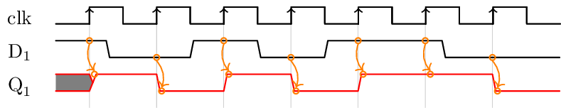
1. Sampling:
A D flip-flop is used to sample the input data. As can be seen on the following timing diagram, the value of input D is captured at each rising edge of the clock. This value is kept until the next rising edge.
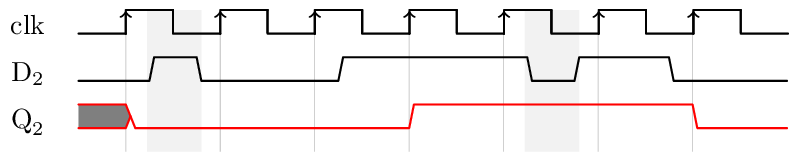
2. Filtering:
A D flip-flop filters transient input changes that occur between clock edges. As indicated the following timing diagram, the changes on the input signal which take less than the clock period do not appear on the output.
Registers
As we often manipulate words (or vectors) of several bits, we will use several flip-flops together. This assembly of flip-flops is called a register.
The symbol of a register is the same as that for a D flip-flop. The size of the register (i.e. the number of bits) is indicated on the input and output of the register:

Initialisation
The initial state of a D flip-flop, when the voltage of the circuit is turned on, is not known. It depends on several factors, including:
-
the technology used to manufacture the circuit,
-
the internal structure of the flip-flop,
-
technological variations between the elements of the same circuit,
-
ambient noise…
In order to obtain a predictable behavior, we need to be able to initialise the flip-flops to a known state. For this, an additional control signal must be used. This particular signal will allow us to force the initial state of a flip-flop.
If the initial state is 0 we speak of reset. If the initial state is
1 we speak of preset.
In the following, we will only consider what is called a synchronous reset. It is effective at the clock edge. Note that the asynchronous reset will be treated in a different lecture in the second semester. A reset can be:
-
positive: initialise the flip-flops when it goes to
1 -
negative: initialise the flip-flops when it goes to
0
It is good practice to add the letter "n" to the name of a reset signal if it is
a negative reset, such as n_reset.
The following figure shows how one can build a flip-flop with a negative synchronous reset:

The timing diagram shows the operation of a synchronous reset:
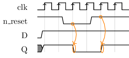
The n_reset signal is of negative polarity, it acts on the flip-flop
when its value is 0. At the following edge of the clock, the flip-flop
is forced to zero. When the n_reset signal returns to 1, the
flip-flop regains its normal operation and the input data is sampled at
the following edge of the clock.
A synchronous reset must follow the same rules as any signal sampled by a D flip-flop.
In general, a synchronous reset is used to functionally initialise parts of the circuit. It is thus generated by another part of the circuit which is also synchronous, which guarantees that it has a duration of at least one clock period.
Generalization
A generic block of sequential logic is represented in the following figure:
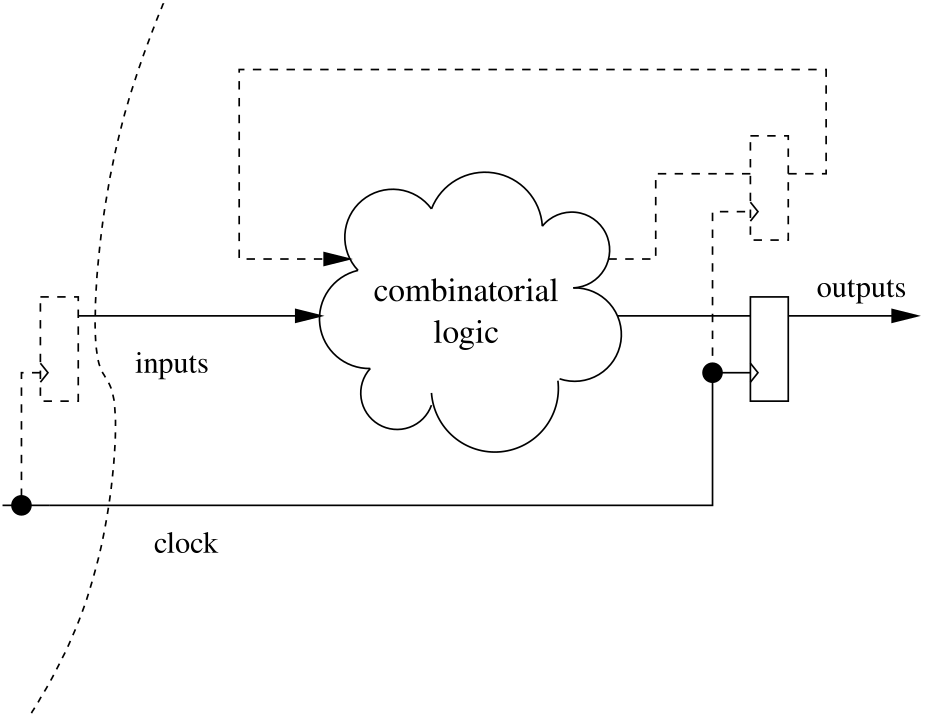
In a block of sequential logic the same clock is used to synchronise all computations. All input signals from the outside world must be sampled. Outputs of combinatorial logic blocks must also be sampled.
These outputs can be:
-
used externally (in another block),
-
or redirected to the inputs of the combinatorial logic.
In the second case we speak of an internal state. The value of the outputs then depends on the value of the inputs and this internal state.
In order for the consecutive output values to be predictable, we must be able to force the initial state. This is done thanks to an external reset signal.