Applications of synchronous logic
In the following, You will find some example applications of synchronous logic.
Shift registers
The following figure shows a shift register made up of four D flip-flops connected serially. This structure is called a shift register with a depth of 4:

The shift register has signal E as input and signal S as output. intermediate signals , and are used to link the output of a flip-flop to the input of the flip-flop that follows it.
The following timing diagram shows the operation of the shift register:

At the first clock tick, the input E is copied to . Then at the following clock ticks, the value of E is shifted from one flip-flop to the next.
Using a shift register
A shift register can be used to delay a signal by an integer number of clock periods. In the previous example, the output S is a copy of input E with four clock periods of delay.
In the same way, the outputs of the flip-flops represent the history of the signal E.
Counters
A counter is an important building block for synchronous sequential logic. The counter’s output is incremented every clock cycle. In order to build a counter we need two elements:
-
a register storing the value (state) of the counter,
-
an incrementer (an adder with one of its inputs tied to ) to calculate the next value.

The above figure shows the schematic of such a counter using an 8-bit register and adder. The initialisation signal reset_n allows to force the initial state and to start counting from zero. Then, at each stroke of the clock, the value of Q is incremented. Since the size of the register and the adder is 8 bits, once the counter reaches 255, it will naturally wrap around to 0 in the following cycle. This is also called a modulo counter.
The following timing diagram shows the evolution of the signals in the counter. Here the reset signal is a synchronous one:
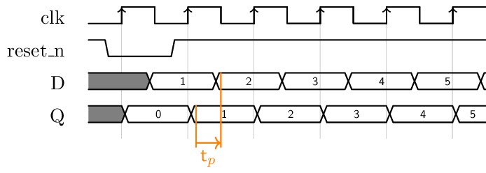
Note that the reset signal acts on the output of the register. Notice also that the output of the adder changes after the output of the register, showing the propagation time of the combinatorial logic.
The pipeline
The pipeline is a technique which makes it possible to increase the operation frequency of a sequential block. It is useful in order to increase the throughput of a data stream.
Consider the following example:

-
A combinatorial function with propagation time
-
Data is presented on inputs A and B at the rate of the clock clk with period .
Note: To simplify the expressions, we neglect in this example the propagation time of the registers.
The system works correctly as long as the following relation between the clock period and the propagation time is satisfied:
The output of the combinatorial block C is sampled and we obtain a result on the output OUT once in every period , as shown in the following timing diagram:

We now decompose into two combinatorial functions and with the respective propagation times and .
- We take care to have and
The point represents the set of signals linking the two combinatorial blocks and :

The system works properly as long as
In the following timing diagram, we have set to be able to compare it to the previous diagram:

Let’s add a register between the combinatorial blocks and . Both blocks are now preceded and followed by registers:

One also says that we have added a pipeline stage.
The system is working properly if the following two conditions are met:
But since the two propagation times and are less than initial propagation time , we can reduce the period of the clock . Or in other words, we can increase the operating frequency and therefore the rate at which the calculations are made1. The new situation is illustrated in the following timing diagram:

Let’s summarize:
-
The pipeline allows to increase the operating frequency.
-
The initial latency increases by the number of pipeline stages.
-
The complexity and size of the circuit has been increased by adding flip-flops and by modifying the initial combinatorial block.
Notice that the first result arrives at the OUT output after two clock periods.